CBCT pre-implant assessment: what to check first

CBCT pre-implant assessment is the systematic reading of the volume to define, on cross-sectional images perpendicular to the ridge, the usable bone height and width, the relationship of the site to critical structures (inferior alveolar canal, mental foramen, lingual concavity, maxillary sinus, nasopalatine canal) and the prosthetic axis, applying a 2 mm safety margin. The American Academy of Oral and Maxillofacial Radiology (AAOMR) recommends cross-sectional imaging for every implant site and considers CBCT the imaging method of choice[1]. Before planning, the whole volume must be read, not only the implant site.
Key points
- The AAOMR recommends cross-sectional imaging of all implant sites, with CBCT as the method of choice[1]; the European Association for Osseointegration (EAO) also requires each exam to be justified and optimized[2].
- Linear measurements on CBCT cross-sections are accurate and reliable, but reported errors include both over- and underestimation, so a 2 mm safety margin to anatomical structures is recommended[3].
- CBCT gray values are not Hounsfield units, and their quantitative use to estimate bone density should be avoided[4].
- At the edentulous mandibular first molar, 66% of ridges showed a lingual concavity (U-type), the morphology where lingual plate perforation risk concentrates[5][6].
- Sinus membrane thickening over 5 mm, especially polypoid, is associated with higher risk of ostium obstruction before sinus floor elevation[7].
- 16.1% of incidental findings on maxillofacial CBCT required intervention or referral, which is why the entire volume must be reviewed[8].
What should a CBCT pre-implant assessment cover?
A complete pre-implant assessment answers seven questions in a fixed order: is the volume diagnostic, are the cross-sections correctly oriented, how much usable bone is there, how far are the critical structures, what do the cortices and trabecular bone look like, does the available bone match the prosthetic axis, and is there anything outside the site that changes management. Following the same sequence every time reduces omissions and produces an auditable report. For the broader planning workflow, see our step-by-step guide to CBCT implant planning; here we focus on the reading method.
Volume quality control before measuring
Before measuring, confirm the exam can answer the clinical question. The FOV must include the entire site and its reference structures (the canal course in the area, the sinus floor, the inferior mandibular border). Patient motion appears as double contours and "split" cortices; beam-hardening artifacts from adjacent restorations and implants produce hypodense streaks that mimic bone defects. Jacobs et al. note that linear accuracy of 200 µm is feasible, yet fivefold inaccuracy levels may be reached with some devices and conditions, and that motion and metal can dramatically degrade image quality[9]. For implant planning, a voxel size of 0.3–0.4 mm provides acceptable diagnostic quality[3]; a smaller voxel increases dose without necessarily improving the decision.
Clinical pearl: if there is motion over the site of interest, rescan or report the limitation. Do not "average" double cortices. A measurement on a non-diagnostic volume is worse than no measurement.
How to measure ridge height and width on cross-sectional images
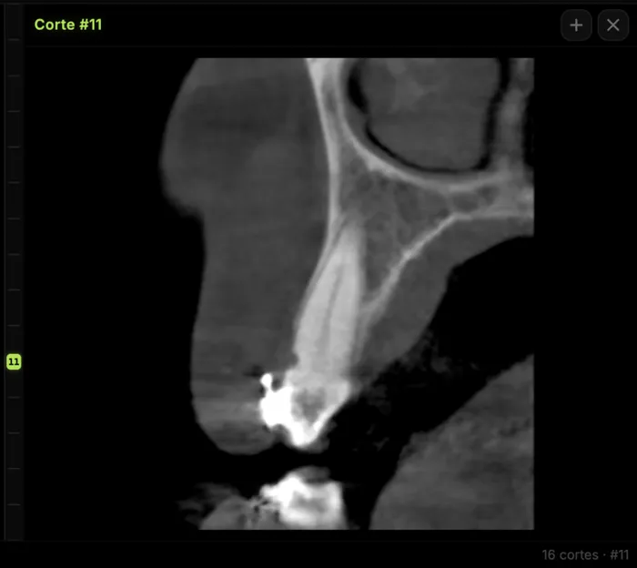
Measure on cross-sectional images (perpendicular to the panoramic curve), never on the reformatted panoramic image, which distorts distances depending on slice position. Orient the volume first: occlusal plane horizontal in the sagittal view and the curve drawn on the axial view along the ridge center. If the curve is not perpendicular to the ridge at that point, the cross-section becomes oblique and overestimates width. Usable height runs from the crest to the upper border of the critical structure (canal roof, sinus floor, or nasal floor), not to its center. Record width at several levels (crestal, mid, apical), because knife-edge ridges or ridges with a lingual concavity may be wide enough at one level and not at another.
The systematic review by Fokas et al. concluded that CBCT linear measurements are accurate and reliable for implant planning, though with an error range that includes over- and underestimation; they recommend a 2 mm safety margin to adjacent structures[3]. This matches the 2 mm zone of safety above the nerve proposed by Greenstein and Tarnow[10].
Critical structures: what to check and report in each region
Each region has its own limiting structure. The inferior alveolar canal and its variants (bifid canals, anterior loop) are covered in our guide to the mandibular canal and inferior alveolar nerve on CBCT. The mental foramen usually lies apical to the second premolar or between the premolar apices, but its position ranges from the canine to the first molar, and radiographic identification of the anterior loop yields a high rate of false positives and negatives[10].
| Region | Structure | What to check | What to report |
|---|---|---|---|
| Posterior mandible | Inferior alveolar canal | Canal roof on cross-sections; buccolingual course | Crest-to-canal-roof distance (mm), 2 mm margin |
| Posterior mandible | Lingual concavity (submandibular fossa) | Ridge shape: convex, parallel, or U-type | Type, depth, and level of the concavity |
| Premolar region | Mental foramen and anterior loop | Mesiodistal and vertical position; mesial continuation | Location, presence and extent of loop if identifiable |
| Symphysis | Lingual canals and foramina | Midline foramina in the lingual cortex | Presence and height relative to the site |
| Posterior maxilla | Maxillary sinus | Residual height, mucosa, septa, ostium patency | Height (mm), type and thickness of mucosal thickening, ostium |
| Anterior maxilla | Nasopalatine canal and facial wall | Canal diameter and position; facial plate thickness | Canal–site relation; facial wall absent, thin, or thick |
Why does the lingual concavity matter at the mandibular first molar?
Chan et al. classified ridge morphology 2 mm above the canal as convex, parallel, or U-type; the U-type was the most prevalent (66%), with a mean undercut depth of 2.4 mm[5]. In a virtual implant placement study by the same group, predicted lingual plate perforation was 1.1–1.2%, and most implants within 1 mm of the lingual plate were in U-type ridges[6]. Height above the canal is meaningless if the implant, at the prosthetic angulation, exits lingually.
Which maxillary sinus findings change the plan?
In 199 sinuses assessed before posterior maxillary implants, 53.6% showed membrane thickening over 2 mm, and residual ridge height was 4 mm or less in 46.9% of first molar sites. Ostium obstruction was associated with membrane thickness (35.3% with thickening over 10 mm) and was more frequent with polypoid thickening; the authors suggest considering ENT referral in such cases before sinus floor elevation[7]. For a broader sinus review, see our clinical guide to the maxillary sinus on CBCT.
How should the facial wall be assessed in the anterior maxilla?
In anterior maxillary sites considered for post-extraction implants, Braut et al. found no facial wall at crest level in 25.7% of teeth and a thin wall (under 1 mm) in 62.9%; in roughly 90% of patients the crestal wall was missing or thin[11]. The report should state whether the facial plate is absent, thin, or thick, since this guides the need for contour augmentation.
Bone quality on CBCT: why not use Hounsfield units
CBCT gray values depend on FOV size, scattered radiation, and the reconstruction algorithm, and they vary between devices and within the same volume. Pauwels et al. conclude that their quantitative use should be avoided for now, and that bone quality assessment is shifting from density toward structural analysis of the trabecular pattern[4]. In practice, describe cortical thickness and trabecular pattern qualitatively, and do not report "density in HU" as if the exam were multidetector CT.
Common errors in pre-implant assessment
| Error | Consequence | How to avoid it |
|---|---|---|
| Measuring on the panoramic reformat | Distorted distances | Measure only on cross-sections |
| Cross-section not perpendicular to the ridge | Overestimated width | Correct the curve and volume orientation |
| Measuring to the canal center | Real margin is lost | Measure to the cortical roof of the canal |
| Window too narrow or too contrasted | Thin cortices "vanish" or thicken | Set window/level before measuring and keep it |
| Ignoring motion or metal artifacts | False defects or inaccurate measurements | Quality control first; report the limitation |
| Reading only the implant site | Relevant findings go unreported | Systematic review of the whole volume |
Prosthetic axis and whole-volume reading
Available bone is only useful if it matches the restoration. Assess the site with a virtual implant oriented to the planned tooth (ideally with a radiographic guide or a digital wax-up), not just along the ridge axis. The EAO stresses that those who prescribe or perform the exam carry justification and optimization obligations, and that the ALARA principle applies, taking alternative techniques into account[2].
Reading the whole volume is not optional. In 300 consecutive maxillofacial CBCT scans, 881 incidental findings were recorded (3.2 per scan); 16.1% required intervention or referral and 15.6% required monitoring[8]. The most common were airway findings (35%) and soft tissue calcifications (20%)[8]. For the radiologist, the report should separate site conclusions (measurements, structures, recommendation) from findings outside the region of interest, each with an explicit recommendation.
What should a pre-implant CBCT report include?
- Technique: device, FOV, voxel size, and quality limitations (motion, artifacts).
- Per site: usable height and width (with levels), distance to the critical structure, ridge morphology, and cortical status.
- Sinus, nasopalatine canal, or mental foramen as relevant, with their relation to the site.
- Findings outside the region of interest and suggested management.
- Key slices as image plates with the measurement visible, so the referring clinician can reproduce it.
How to do it in CBCTHub
CBCTHub lets you perform this reading in the browser, with nothing to install and the DICOM processed locally. For a pre-implant assessment:
- Open the exam from the link sent by the imaging center, or drag the DICOM into the web viewer.
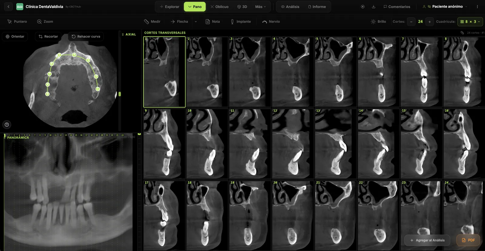
- In the MPR view, orient the volume and draw the panoramic curve on the axial slice; the viewer generates the cross-sectional grid.
- Measure height, width, and distance to the canal roof or sinus floor in millimeters on each cross-section.
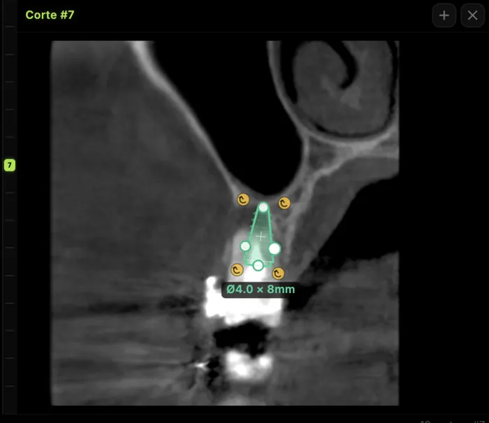
- Place a virtual implant with the planned diameter and length to check margins and axis.
- If you need help tracing the canal, AI segmentation shows it in 3D with the adjacent roots; always confirm the final decision on the slices.
- Write the report in the editor, build PDF image plates, and leave comments on specific slices for the referring clinician.
For radiologists and imaging centers: deliver the scan and the report to referring dentists by link, no CDs, on an exam page with your center's branding and PIN access. For implant surgeons and dentists: open and measure the CBCT your imaging center sends you, right in the browser. Try the viewer free, no account needed, or create a CBCTHub account.
Conclusion
CBCT pre-implant assessment is a method, not a single measurement: quality control, correct orientation, measurements on cross-sections to the border of the critical structure with a 2 mm margin, qualitative bone description, verification against the prosthetic axis, and reading the entire volume. This article is information for professionals and does not replace clinical judgment or case-by-case evaluation.
Frequently asked questions
Is CBCT mandatory before placing an implant?
There is no universal mandate, but the AAOMR recommends cross-sectional imaging for the assessment of all implant sites and considers CBCT the imaging method of choice to obtain it. The EAO adds that every exam must be justified and optimized, applying the ALARA principle and considering alternatives that achieve the same objective with lower dose.
What safety margin should be kept from the inferior alveolar canal?
A 2 mm margin between the implant tip and the upper border of the inferior alveolar canal is recommended. The systematic review by Fokas et al. supports it based on the error range of CBCT linear measurements, which includes both over- and underestimation, and it matches the zone of safety proposed by Greenstein and Tarnow for the nerve.
Which voxel size is appropriate for implant planning?
According to the systematic review by Fokas et al., a voxel size of 0.3–0.4 mm provides acceptable diagnostic quality for implant treatment planning. A smaller voxel usually increases dose and noise without changing the decision, so choose the protocol according to the clinical question and the smallest FOV that covers it.
Can bone density be measured in Hounsfield units on CBCT?
Not reliably. CBCT gray values vary with FOV, scattered radiation, and the reconstruction algorithm, and they are not equivalent to multidetector CT Hounsfield units. Pauwels et al. recommend avoiding their quantitative use and describing bone quality qualitatively, based on cortical thickness and trabecular pattern rather than numeric density values.
Why read the whole volume if only an implant was requested?
Because findings outside the site are common and some change management. In a series of 300 maxillofacial CBCT scans, there were 3.2 incidental findings per scan, and 16.1% of them required intervention or referral. Whoever reports the exam is responsible for describing what the entire acquired volume shows, not only the region of interest.
When should sinus membrane thickening prompt a referral?
Thickening over 5 mm, especially polypoid, is associated with a higher risk of maxillary ostium obstruction. In such cases, Shanbhag et al. suggest considering ENT referral before sinus floor elevation. The report should describe membrane thickness, mucosal morphology, and ostium patency so the surgeon can weigh the decision with the referring physician.
References
- Tyndall DA, Price JB, Tetradis S, Ganz SD, Hildebolt C, Scarfe WC; American Academy of Oral and Maxillofacial Radiology. Position statement of the American Academy of Oral and Maxillofacial Radiology on selection criteria for the use of radiology in dental implantology with emphasis on cone beam computed tomography. Oral Surg Oral Med Oral Pathol Oral Radiol. 2012;113(6):817-26. doi:10.1016/j.oooo.2012.03.005
- Harris D, Horner K, Gröndahl K, Jacobs R, Helmrot E, Benic GI, et al. E.A.O. guidelines for the use of diagnostic imaging in implant dentistry 2011. A consensus workshop organized by the European Association for Osseointegration at the Medical University of Warsaw. Clin Oral Implants Res. 2012;23(11):1243-53. doi:10.1111/j.1600-0501.2012.02441.x
- Fokas G, Vaughn VM, Scarfe WC, Bornstein MM. Accuracy of linear measurements on CBCT images related to presurgical implant treatment planning: a systematic review. Clin Oral Implants Res. 2018;29 Suppl 16:393-415. doi:10.1111/clr.13142
- Pauwels R, Jacobs R, Singer SR, Mupparapu M. CBCT-based bone quality assessment: are Hounsfield units applicable? Dentomaxillofac Radiol. 2015;44(1):20140238. doi:10.1259/dmfr.20140238
- Chan HL, Brooks SL, Fu JH, Yeh CY, Rudek I, Wang HL. Cross-sectional analysis of the mandibular lingual concavity using cone beam computed tomography. Clin Oral Implants Res. 2011;22(2):201-6. doi:10.1111/j.1600-0501.2010.02018.x
- Chan HL, Benavides E, Yeh CY, Fu JH, Rudek IE, Wang HL. Risk assessment of lingual plate perforation in posterior mandibular region: a virtual implant placement study using cone-beam computed tomography. J Periodontol. 2011;82(1):129-35. doi:10.1902/jop.2010.100313
- Shanbhag S, Karnik P, Shirke P, Shanbhag V. Cone-beam computed tomographic analysis of sinus membrane thickness, ostium patency, and residual ridge heights in the posterior maxilla: implications for sinus floor elevation. Clin Oral Implants Res. 2014;25(6):755-60. doi:10.1111/clr.12168
- Price JB, Thaw KL, Tyndall DA, Ludlow JB, Padilla RJ. Incidental findings from cone beam computed tomography of the maxillofacial region: a descriptive retrospective study. Clin Oral Implants Res. 2012;23(11):1261-8. doi:10.1111/j.1600-0501.2011.02299.x
- Jacobs R, Salmon B, Codari M, Hassan B, Bornstein MM. Cone beam computed tomography in implant dentistry: recommendations for clinical use. BMC Oral Health. 2018;18(1):88. doi:10.1186/s12903-018-0523-5
- Greenstein G, Tarnow D. The mental foramen and nerve: clinical and anatomical factors related to dental implant placement: a literature review. J Periodontol. 2006;77(12):1933-43. doi:10.1902/jop.2006.060197
- Braut V, Bornstein MM, Belser U, Buser D. Thickness of the anterior maxillary facial bone wall: a retrospective radiographic study using cone beam computed tomography. Int J Periodontics Restorative Dent. 2011;31(2):125-31. PMID:21491011
Try CBCTHub for free
Upload, view, and share DICOM scans in the cloud. Nothing to install.
Create free accountRelated articles

Browser DICOM viewer vs desktop: what works for CBCT in clinic
Open CBCT in the browser or install a desktop viewer? A clinical decision matrix: MPR performance, offline use, Mac/Windows mix, sharing without CDs, and when native software still wins.

How to open a CBCT without installing software: a practical online-viewer guide
You got a CD, ZIP, or link with a CBCT and no manufacturer viewer. How to open the DICOM in the browser, measure in mm, and what to do when it fails.

Mandibular canal and inferior alveolar nerve on CBCT: anatomy, variants, and pre-surgical measurement
Locate the mandibular canal and IAN on CBCT: mental loop, bifid/retromolar canal, measurement checklist, and when to escalate from panoramic (ALADA).