Ridge height and width on CBCT: measurements and pitfalls

Alveolar ridge height and width on CBCT are measured on cross-sectional slices perpendicular to the arch curve, along the planned restorative axis rather than the true vertical: usable height runs from the crest to 2 mm short of the critical structure, and width is recorded at no fewer than three levels. CBCT linear measurements are accurate and reliable, but errors go in both directions, which is why systematic reviews recommend a 2 mm safety margin[1]. Most measurement errors come not from the scanner but from how the slice is oriented, windowed and read.
Key points
- A systematic review by Fokas et al. (22 studies) found CBCT linear ridge measurements accurate and reliable, with both over- and underestimation, and recommended a 2 mm margin to adjacent anatomic structures[1].
- In cadaver heads scanned at a 0.3 mm voxel, the mean absolute difference between CBCT and direct measurement was 0.30 mm for buccal bone height and 0.13 mm for buccal bone thickness[2].
- A buccal plate needed about 0.17 mm of thickness to be visible on high-resolution MPR, and the lingual plate roughly twice that; 3D rendering performed worst on lingual surfaces[3].
- In more than 3,000 implants, facial bone loss decreased significantly as residual facial bone thickness approached 1.8–2 mm[4].
- The American Academy of Oral and Maxillofacial Radiology (AAOMR) recommends cross-sectional imaging for all implant sites, with CBCT as the method of choice[5].
What are usable ridge height and ridge width on CBCT?
Usable height is the distance from the alveolar crest to the boundary the implant must not reach, minus the safety margin. In the posterior mandible that boundary is the superior cortical border (roof) of the mandibular canal; in the posterior maxilla, the cortical sinus floor; in the anterior maxilla, the nasal floor and the nasopalatine canal; in the symphysis, the basal cortex and lingual foramina. Measuring to the center of the canal instead of its roof overestimates height by half the canal diameter.
Width is the buccolingual (or buccopalatal) bone dimension measured perpendicular to the planned implant axis. A single crestal value does not describe the ridge: knife-edge ridges are narrow at the top and wide below, while ridges with a lingual undercut do the opposite. Record width at three levels — crestal, mid and apical — and note the distance from the crest for each one.
For the broader pre-implant read (volume quality control, sinus, mental foramen, restorative axis), see our CBCT pre-implant assessment guide. This article focuses on the measurement itself and its pitfalls.
How to measure ridge height and width on CBCT, step by step
- Check the volume before measuring. Patient motion, metal artifacts, device-specific exposure parameters and the software used all reduce measurement accuracy in clinical practice[1]. If the site is degraded by artifact, say so before you hand over a number.
- Reorient the volume. Align the occlusal plane or the ridge on the sagittal and coronal views.
- Draw the panoramic curve through the center of the ridge on the axial slice, at the level of the site. Cross-sections are generated perpendicular to that curve; if the curve does not follow the ridge at that point, the slice is oblique.
- Pick the right cross-section. Center it mesiodistally on the site and scroll the neighboring slices: a defect may sit 1–2 mm mesial or distal.
- Set the implant axis. Use the radiographic guide or the planned tooth if available. Height is measured along that axis; width, perpendicular to it.
- Measure with a stable window and zoom. A narrow window or a high level "erases" thin cortices and shortens width; zoom in enough to place the calipers on the edges, and do not measure on a thickened slab.
- Record and subtract the margin. Report the height to the critical structure and, separately, the usable height with the 2 mm margin already subtracted, so the referring clinician does not have to do the math.
How much does width change if the cross-section is oblique?
It is simple geometry: if the slice crosses the ridge at an angle θ from the perpendicular, measured width is multiplied by 1/cos θ. At 20° off, an 8.0 mm ridge reads as 8.5 mm; at 30°, as 9.2 mm. The error always overestimates, which is exactly the dangerous direction. Check on the axial view that the slice line crosses the ridge at a right angle, especially in the canine region where the arch turns.
How accurate are CBCT linear measurements?
The evidence supports CBCT for ridge measurement, with caveats that matter when you report.
| Study | Design | Main finding | Practical implication |
|---|---|---|---|
| Fokas et al., 2018[1] | Systematic review, 22 studies (2 clinical, 20 ex vivo) | High accuracy and reliability; both over- and underestimation; 0.3–0.4 mm voxel adequate | 2 mm safety margin to adjacent structures |
| Timock et al., 2011[2] | 12 cadaver heads, 65 teeth, 0.3 mm voxel | Mean absolute difference 0.30 mm (buccal bone height) and 0.13 mm (buccal thickness); no systematic bias | Height is more reproducible than plate thickness |
| Jacobs et al., 2018[6] | Narrative review with recommendations | Accuracies of 200 µm are feasible, but some machines reach fivefold larger errors | Evidence from one scanner does not automatically apply to another |
| Lennholm et al., 2024[3] | Ex vivo with histology, 0.125 mm voxel | Minimum visible thickness: 0.173 mm buccal and 0.356 mm lingual on high-resolution grayscale MPR | Very thin plates may be present yet invisible |
Most of these data come from ex vivo studies without patient motion; clinical error is usually larger, which is the whole point of the 2 mm margin[1].
Buccal bone thickness: the limit of what you can see
Buccal plate thickness is one of the most relevant measurements and also one of the most fragile. Spray et al. found, in more than 3,000 implants, that bone loss decreased significantly as residual facial bone approached 1.8–2 mm[4]. Ridge width therefore has to be read against the implant diameter and the bone that will remain on each side, not as a standalone number.
The catch is that thin plates sit close to the resolution limit. Lennholm et al. compared CBCT with histology: validity was best with high resolution, MPR and grayscale; the thickness needed to see the plate was twice as large lingually as buccally, and 3D rendering had the lowest validity on lingual surfaces[3].
Reporting pearl: if you cannot see the buccal plate, write "buccal plate not discernible on CBCT", not "absent buccal plate". Bone may be present below the visibility threshold, and that distinction changes the conversation with the surgeon.
Common ridge measurement pitfalls and how to avoid them
| Pitfall | Effect | How to avoid it |
|---|---|---|
| Measuring on the reconstructed panoramic | Distances depend on the curve and reconstruction thickness | Measure only on cross-sections[5] |
| Cross-section oblique to the ridge | Overestimated width (1/cos θ factor) | Confirm on the axial view that the slice is perpendicular |
| Measuring height along the vertical, not the implant axis | Values that do not match the implant's real path | Define the restorative axis first |
| Measuring to the canal center | Overestimated usable height | Measure to the canal roof and subtract 2 mm[1] |
| Recording crestal width only | Missed lingual undercuts | Measure at three levels and describe the morphology |
| Narrow window or 3D rendering for thin plates | "Erased" cortices; underestimated width or plate reported as absent | Grayscale MPR with a wide window[3] |
| Ignoring motion or metal artifacts | Double or blurred edges; unreliable values | Report the limitation and, if needed, withhold the measurement[1] |
| Assuming every scanner measures the same | False sense of precision | Know the performance of your own unit and protocol[6] |
Why does mid-ridge width matter so much at the mandibular first molar?
Chan et al. found that, 2 mm above the mandibular canal at the first molar site, 66% of ridges had a lingual undercut (U-type) morphology, with a mean undercut depth of 2.4 mm[7]. In the same group's virtual implant study, most implants within 1 mm of the lingual plate were in U-type ridges[8]. Adequate crestal width does not rule out lingual perforation if the mid-ridge narrows. The implant–nerve relationship is covered in our guide to the mandibular canal and inferior alveolar nerve on CBCT.
Does a smaller voxel measure better?
Not necessarily. For implant planning, a 0.3–0.4 mm voxel provides images of acceptable diagnostic quality[1]. A small voxel makes sense when the question is the thickness of a thin plate, as in Lennholm's study at 0.125 mm[3]. Because effective doses across CBCT devices span a range in which the lowest is almost 100 times lower than the highest, and dose drops when exposure is adjusted and the FOV is restricted to the region of interest[9], the protocol should answer the clinical question rather than chase maximum resolution. See also our CBCT image quality checklist.
What the ridge height and width report should include
- Site with tooth number (FDI or Universal, as your referrers use) and the reference cross-section number.
- Height to the critical structure and usable height with the 2 mm margin subtracted, naming the limiting structure.
- Width at three levels, with the distance from the crest for each.
- Ridge morphology: knife-edge, lingual undercut, vertical or buccal defects.
- Buccal plate: thickness if measurable, or "not discernible" if not seen.
- Volume limitations: motion, artifacts, a FOV that does not include the limiting structure.
When you communicate findings to the referring clinician, pair every number with the slice it came from. A bare number gets re-interpreted; an annotated slice is understood at once.
How to do it in CBCTHub
CBCTHub lets you measure ridge height and width in the browser on the CBCT your imaging center delivers, with nothing to install. DICOM files are processed locally in the browser, and scans from Carestream, Planmeca, Vatech, Sirona, Morita, NewTom and other units are supported.
- Open the study from the center's link or load the DICOM into the viewer.
- Generate the panoramic and cross-sections from the arch curve; adjust the curve point by point if it does not follow the ridge center.
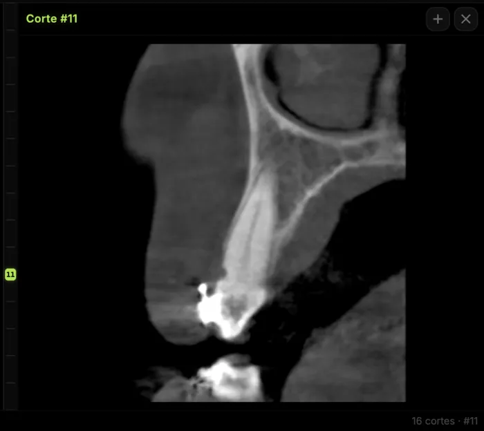
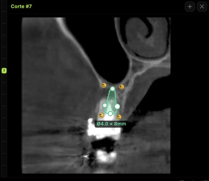
- On the site's cross-section, use the mm measurement tool for height to the canal roof or sinus floor, and for width at three levels.
- Place a virtual implant with the planned diameter and length to check the real distance to the cortices and critical structures.
- Leave a comment on the slice, or build PDF image plates in the report editor to send to the referring clinician.
For radiologists and imaging centers: deliver the scan and report to referring dentists by link, no CDs, on a study page carrying your center's branding. For implant surgeons and dentists: open and measure the CBCT your center sends you, right in the browser. Try the viewer free with no account at cbcthub.com/viewer or create an account at cbcthub.com.
Conclusion
Measuring ridge height and width on CBCT is reliable when done on well-oriented cross-sections, along the restorative axis, with a 2 mm margin to the critical structure[1]. The errors that matter most are methodological: oblique slices, measuring to the canal center, stopping at crestal width, or calling a plate absent when it is below the visibility threshold[3]. A report that gives usable height, width at three levels, morphology and limitations prevents back-and-forth and changes decisions. This content is for professionals and does not replace clinical judgment.
Frequently asked questions
Where does ridge height measurement start and end on CBCT?
It starts at the highest point of the alveolar crest at the site and follows the planned implant axis to the boundary of the critical structure: the roof of the mandibular canal cortex, the sinus floor, the nasal floor or the basal cortex. A 2 mm safety margin is then subtracted, as recommended by the Fokas et al. systematic review to compensate for measurement error in CBCT.
At how many levels should ridge width be measured?
Measure at least three levels: crestal, mid and apical, always perpendicular to the implant axis and noting the distance from the crest. A single crestal value misses knife-edge ridges and lingual undercuts. At the mandibular first molar, lingual undercut morphology is common, so the mid-ridge width may be the value that actually defines perforation risk during implant placement.
What is the measurement error of CBCT on the alveolar ridge?
Ex vivo, the mean absolute difference against direct measurement was 0.30 mm for buccal bone height and 0.13 mm for buccal thickness. However, error can go in either direction and increases with patient motion, metal artifacts, the scanner and the software. That is why a 2 mm safety margin to adjacent anatomic structures is recommended when planning implants on CBCT.
If the buccal plate is not visible on CBCT, is it absent?
Not necessarily. In a histology-controlled study, a buccal plate needed about 0.17 mm of thickness to be visible on high-resolution MPR, and the lingual plate roughly twice that. Thinner plates can exist without being seen. The safer wording is "not discernible on CBCT" rather than "absent", and 3D renderings should not be used to judge thin plates.
References
- Fokas G, Vaughn VM, Scarfe WC, Bornstein MM. Accuracy of linear measurements on CBCT images related to presurgical implant treatment planning: a systematic review. Clin Oral Implants Res. 2018;29 Suppl 16:393-415. doi:10.1111/clr.13142
- Timock AM, Cook V, McDonald T, Leo MC, Crowe J, Benninger BL, et al. Accuracy and reliability of buccal bone height and thickness measurements from cone-beam computed tomography imaging. Am J Orthod Dentofacial Orthop. 2011;140(5):734-44. doi:10.1016/j.ajodo.2011.06.021
- Lennholm C, Andreasen H, Westerlund A, Lund H. Visibility of alveolar bone thicknesses on CBCT images: a study on minimum bone requirements using various reconstruction techniques, viewing modes, and resolutions. Clin Oral Investig. 2024;28(12):641. doi:10.1007/s00784-024-06034-1
- Spray JR, Black CG, Morris HF, Ochi S. The influence of bone thickness on facial marginal bone response: stage 1 placement through stage 2 uncovering. Ann Periodontol. 2000;5(1):119-28. doi:10.1902/annals.2000.5.1.119
- Tyndall DA, Price JB, Tetradis S, Ganz SD, Hildebolt C, Scarfe WC. Position statement of the American Academy of Oral and Maxillofacial Radiology on selection criteria for the use of radiology in dental implantology with emphasis on cone beam computed tomography. Oral Surg Oral Med Oral Pathol Oral Radiol. 2012;113(6):817-26. doi:10.1016/j.oooo.2012.03.005
- Jacobs R, Salmon B, Codari M, Hassan B, Bornstein MM. Cone beam computed tomography in implant dentistry: recommendations for clinical use. BMC Oral Health. 2018;18(1):88. doi:10.1186/s12903-018-0523-5
- Chan HL, Brooks SL, Fu JH, Yeh CY, Rudek I, Wang HL. Cross-sectional analysis of the mandibular lingual concavity using cone beam computed tomography. Clin Oral Implants Res. 2011;22(2):201-6. doi:10.1111/j.1600-0501.2010.02018.x
- Chan HL, Benavides E, Yeh CY, Fu JH, Rudek IE, Wang HL. Risk assessment of lingual plate perforation in posterior mandibular region: a virtual implant placement study using cone-beam computed tomography. J Periodontol. 2011;82(1):129-35. doi:10.1902/jop.2010.100313
- Bornstein MM, Scarfe WC, Vaughn VM, Jacobs R. Cone beam computed tomography in implant dentistry: a systematic review focusing on guidelines, indications, and radiation dose risks. Int J Oral Maxillofac Implants. 2014;29 Suppl:55-77. doi:10.11607/jomi.2014suppl.g1.4. PMID: 24660190
Try CBCTHub for free
Upload, view, and share DICOM scans in the cloud. Nothing to install.
Create free accountRelated articles

CBCT pre-implant assessment: what to check first
CBCT pre-implant assessment, step by step: cross-sectional measurements, the 2 mm safety margin, critical structures and what the report must include.

Browser DICOM viewer vs desktop: what works for CBCT in clinic
Open CBCT in the browser or install a desktop viewer? A clinical decision matrix: MPR performance, offline use, Mac/Windows mix, sharing without CDs, and when native software still wins.

How to open a CBCT without installing software: a practical online-viewer guide
You got a CD, ZIP, or link with a CBCT and no manufacturer viewer. How to open the DICOM in the browser, measure in mm, and what to do when it fails.